3 Watt LED Bike Light
Experiments
May, 2008, Rev
d.2
Michael Krabach
Contents
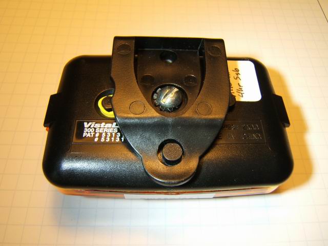
Prototype 11 – Yellow Rear Multi-mode Flasher with no Optics
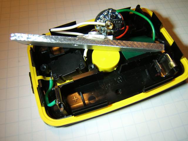
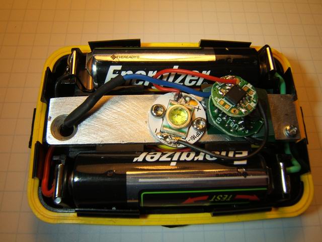
The difficulty of finding or building a container for prototype 10 resulted in modifying a VistaLite flasher to house a single LED. It was found from prototype 10 that the warning flasher mode (aka police mode) did not generate any appreciable heat in the heat sink. I decided to use a small heat sink that would replace the original circuit board which resided between the two battery compartments. The location of screw holes holding down the heat sink (originally the circuit board), prevented centering a full size star LED within the case. So a 16mm diameter base LED was used. The DX SKU-3417 is a 3 watt white LED. Since the LED lens appeared loose, I decided to screw the base to the heat sink instead of bonding, so it could be removed if it proved defective. Heat paste was used under the LED base. Since a flasher was desired, a regulator/controller was chosen different from prototype 10. A controller was found that had a flasher mode, but did not have the feature of keeping the last mode after being turned off. I decided to use the DX SKU-10084 (which comes with pre-wired output leads) which has an input voltage from 1-3 volts (no adjustment available) and has 5 modes. The double circuit board controller is seen in the photos below. The bottom board is the regulator and the top is the user interface (UI). The clicky switch fits in the same spot where the original switch was located, seen in the center photo below. Trim the switch leads so they do not touch the back of the aluminum heat sink. The controller is located as close to the center of the unit and had to be squashed slightly to fit under the snap-on amber cover. A red snap-on cover is also available, but the yellow is much brighter when using a white LED.
The prototype uses 2 AA batteries and draws 700 ma on high and 230 ma on low, steady mode. The voltage across the LED is 3.24v on high, 2.0v on low. The unit will run on one AA, for which the voltage across the LED is 2.98V on high, and 2.14 on low. When turned on, the LED is on high. A single quick click off/on drops the light to low. The clicky switch works well because it can be depressed slightly as a break/make switch. Subsequent clicks change to the slow strobe, the fast strobe and then to a beacon mode, which is a flash every 8 seconds. With NiMH batteries the unit will strobe about 4 hours. When the battery (no load) voltage reaches about 1.1 volt, the flashing mode will not work, but the steady modes still work. This flasher is used by clipping the flasher to a bikers clothing or rear bike bag. The photos below show the finished prototype. As a caution flasher it is very bright, almost as bright as some strobe lights. I recommend that it only be used in the low or strobe modes where the unit only reaches about 100 deg F. In the high mode the heat sink will not be able to handle the emitter heat since the heat sink is enclosed in a plastic case.