
3 Watt LED Bike Light
Experiments
June, 2008,
Rev f
Michael Krabach
Contents
Prototype 16 – Red flasher two LEDs Clear Case
Trying to find an old
Vistalite flasher for modification is almost impossible unless you
happen to have one. Rear flashers tend to get broken or thrown away
when new ones are introduced. So the problem is to find a suitable
case that is splash proof, and can be clamped on the bike easily was
difficult. I also looked at PVC pipe fittings and copper fittings.
None was going to be an easy adaptation. Almost all the flashers now
are AAA double battery models. I only found one AA version but did
not have the room inside to mount the star LED. It also cost $10. The
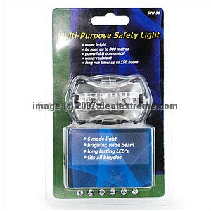
best I could find that is cheap, since it was going to be gutted
anyway, is a dealextreme.com model DX
SKU-1211 which is listed as $3.25. Certainly a price in line with
these experiments
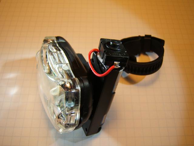
The unit is gutted, removing the original
strip of LEDs and the battery posts. Two small screws under the LED
strip are removed to get access to the rubber carbon tip switch.
Remove it and cut off the silicon rubber post. Use a push pin to poke
a small hole through the silicon button for future wire penetration.
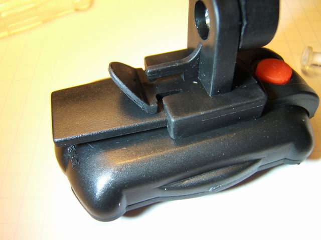
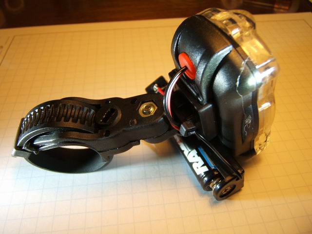
Attach the seat post clamp to the flasher. And note where the locking
tab falls into a notch on the flasher belt clip. Take a fine hacksaw
and cut off the end of the belt clip and use snips to cut off the end
of the locking tab. The original assembly is seen in photo 3 below
with the seat post assembly clipped on the belt clip. The next photo
shows the final result after bolting (glues will not make a good bond
with the plastic body of the flasher) a single AA battery holder to
the flasher. I used small bolts (2-56) that pass through the holder
and the flasher case. Note that the bolts are tight with the edge of
the battery holder to allow the AA battery to seat down in the
holder.
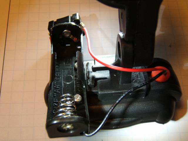
A clicky
switch is attached to the end of the battery holder using a
urethane glue. The mating surfaces of the battery holder and the
switch are sanded for a better bond. This glue is adequate for the
limited stress on this bond. The red wire from the battery holder is
cut and the switch terminals are soldered in line. The wires are then
poked through the pin hole in the silicone button to emerge in the
case.
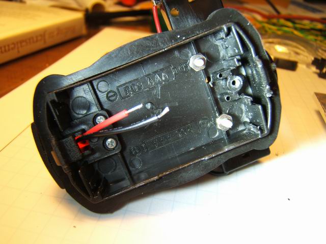
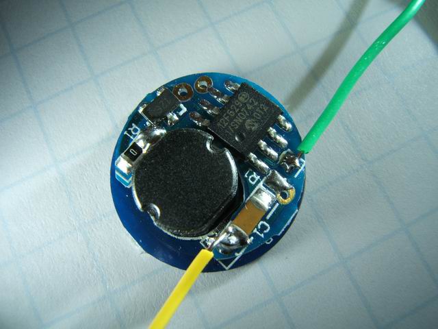
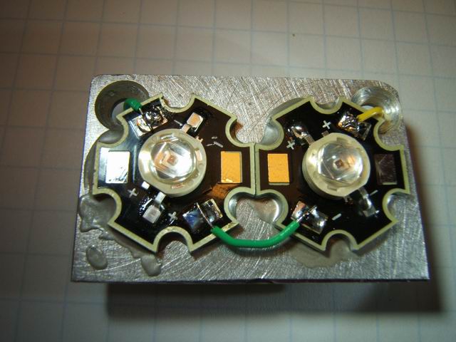
The regulator used is the same as prototype 13 and 15 (DX SKU-7302) which supplies 3.7v to the two LEDs in series. The original wires that came attached to the regulator were too thin (I had wires break in one of the other prototypes.) and I replaced them as seen in the first photo below. For this prototype I used the generic red LEDs that were used in prototype 13 because, I had some, and with the clear lens I wanted to see what the lesser LEDs would do before trying Cree LEDs. The star LEDs are bonded to the heat sink plate (hand cut 1/8” Al) with Arctic Silver Thermal Adhesive. The bottom of the heat sink has a piece of electrical tape to prevent shorting. The (+) and (-) wires are soldered to the regulator in the last photo.

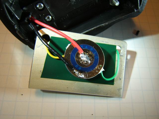
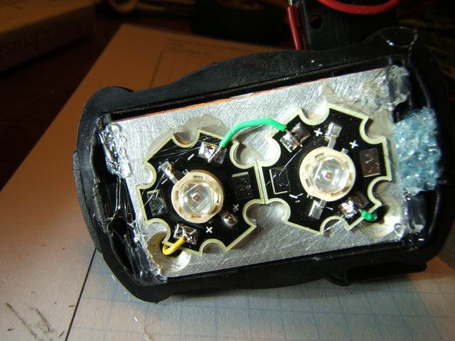
The heat sink plate is held in the flasher body by a small amount of urethane glue at the corners of the housing. This is only to keep the LED assembly from bouncing around inside, There is no room for any other means of attachment. The final flasher is seen in the last two photos.
(Directions
to configure modes and groups.)
(1) Low, Med, High, Fast
strobe, SOS
(2) Low, Med, High
(3) Low, Med, High, Fast strobe,
Police strobe, Med strobe, Slow strobe, Beacon strobe, SOS
This
regulator remembers the last setting when turned off.