
3 Watt LED Bike Light
Experiments
February, 2008,
Rev c
Michael Krabach
Contents
Prototype 7 - Triple SSC in “C” Mag-lite Head
This was an attempt to upgrade the “Cheap 20 watt Bike Light” with LEDs. This light uses a 2 cell “C” Mag-lite head. (Specifically the silver model.) It happened that a specific DX SKU-4630 triple lens would fit the depth of this Mag-lite head with minor adjustment on the lens standoffs. If you don't have a Mag-lite around to hack apart the prototype will cost you from $14-18 more.
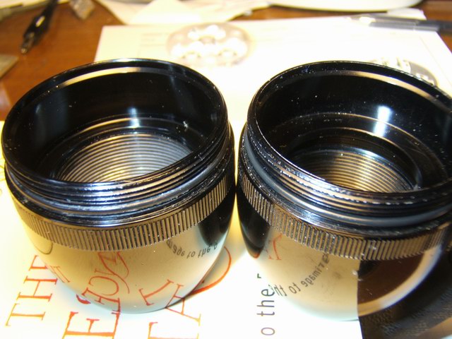
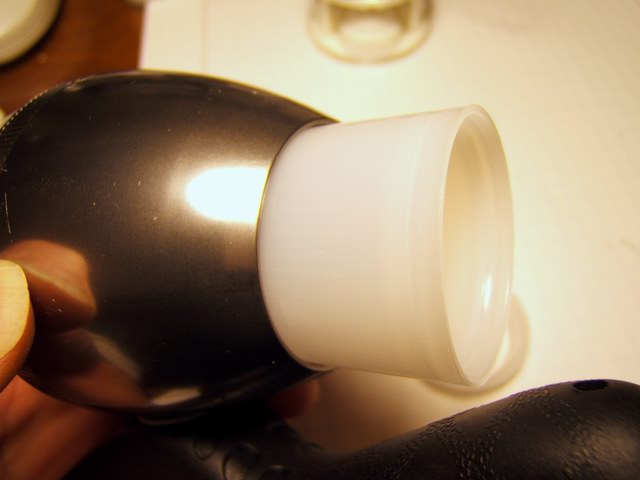
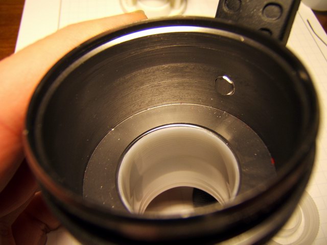
In the process of working with several Mag-lites I found that all Mag-lite are not constructed the same, even within each “C” or “D” category. Not only have the switches changed, but the internal machining and o-ring placement changes. So any design based on a Mag-lite that uses tri-optic lens must be built with a lens that fits that Mag-lite or can be adjusted to fit. This is especially true if you depend on the bezel tightening down to hold the LED assembly in place. If you have a design that fastens the reflectors or lens to the LEDs, and can attach (cap screws) the heat sink to the light head your design can be more flexible. I did not have the tools to tap screw holes small enough to fit in the tight space. The Mag-lite photos below show some differences in the head designs. In the left photo, the head on the left is a silver “C” cell depth 27 mm, (not shown, purple “C” cell depth 24 mm.), and on the right a black 3 “D” cell depth 16 mm. In the right photo, the head on the left is a black 2 “D” cell depth 19 mm, and on the right a black 3 “D” cell depth 16 mm. ( The same 3 “D” cell is on right in both photos.)
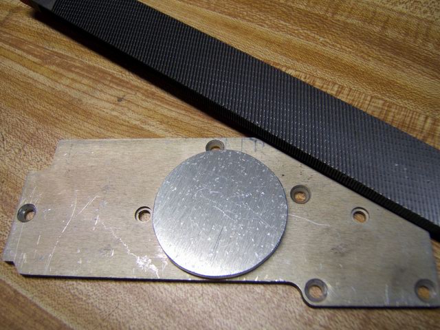
A round mounting plate and heat sink had to be hacksawed from a 1/8” scrap of aluminum. That takes about ½ hr with a good hacksaw and coarse rasp. A hole must be drilled exactly in the center for the power wires to pass through from the back. I sanded the top and bottom of the plate to make sure it was flat and would bond the LEDs well. It will drop into the head and rest on the bottom land. Thermal paste will complete the thermal contact for heat transfer.

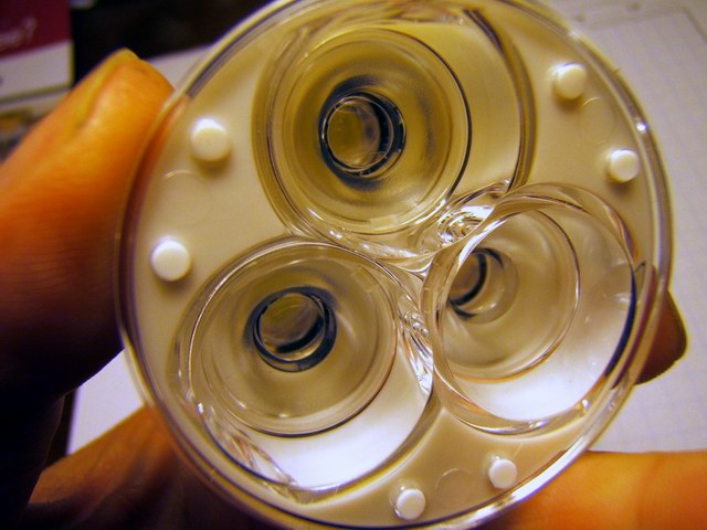
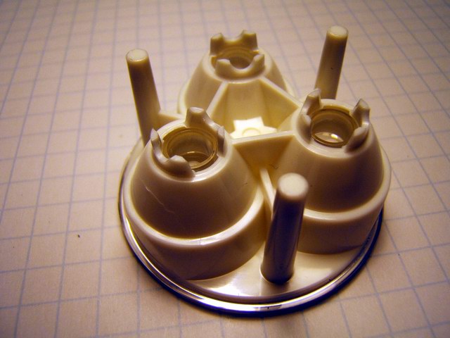
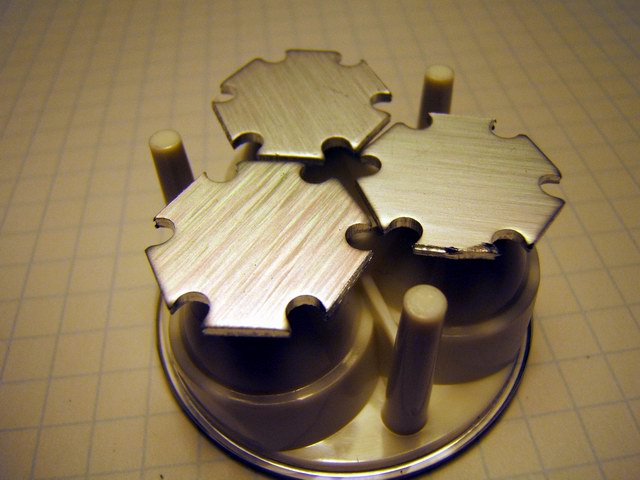
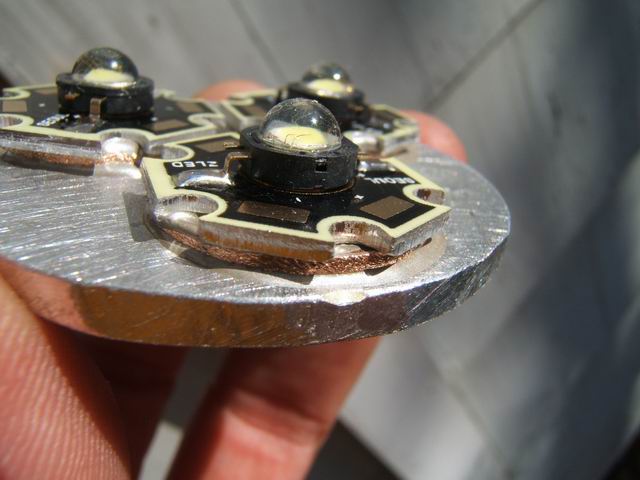
This DX SKU-4630 triple lens was designed specifically for the SSC LEDs and does not focus the Cree LEDs. So this unit has three 3 watt SSC LEDs in series while using a 12 volt gel cell. The photos below show the progression in setting up the star LEDs and the optics. The stars are placed (notches in optics hold them) into their sockets as in photo 3. With the mounting slug placed on the bottom in photo 4 you can see there is clearance that need to be reduced. In this case by snipping off bottom of the optic feet.
![]()
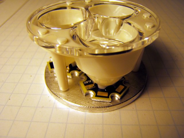
The assembly must fit in the Mag-lite head perfectly and the following details the gruesome procedure. I snapped the stars onto the optics as in photo 3 above. The orientation of the stars should be + to – and + to – and + to – so the series wiring will be minimal. You can see the polarity pattern in a photo below. Then with the head facing up, insert the slug and carefully put the tri-optic (with the stars attached) into the head. Turn over the unit and lift of the head, leaving the aligned slug and optics in position. I then carefully marked with a pencil where the stars were on the slug. Then using Arctic Silver epoxy I attached the star LEDs to the marked areas on the slug. Use the epoxy sparingly. Close but not exact alignment is required. Remember to make sure the polarity orientation is correct. The epoxy will cure in 15 minutes so you don't have a lot of time to waste. Snap the tri-optic over the stars and press down on the optics to squeeze out any excess epoxy. Clean any excess from the edges with a Q tip and alcohol. Carefully take the whole unit and flip it over so the tri-optic is facing down. Place the Mag-lite head over the heat sink plate, LEDs and tri-optic. Slip a piece of stiff paper under the assembly and carefully, turn it over and make sure that the optics are centered in the head as in the last photo below. Put pressure on the optics while it sets. Keep any excess epoxy on a piece of paper so you can monitor the curing process. When the epoxy seems to have firmed up, but not cured, you can flip the unit over and lift off the head carefully to make sure epoxy has not smeared on the walls of the head. If the assembly looks good, place the head back over the assembly and let the curing finish.
Note in photo 2 below one of the LEDs was found to be bad and is not wired. Always check the LEDs before epoxying to anything. To remove the bad emitter, I had to Dremel grind the copper emitter backing from the star backing, It had to be ground down to the point it was paper thin (to minimize the thermal mass) before I could use a soldering iron to remove the last of the copper slug. I later used Arctic Silver to bond a new emitter on the star. Lesson learned!

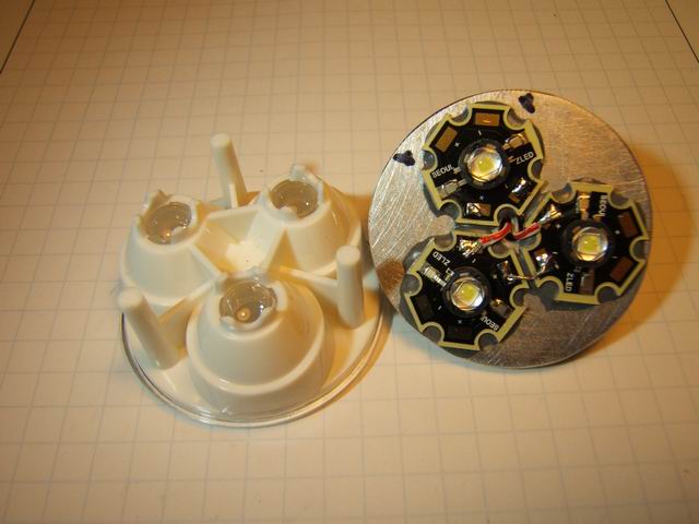
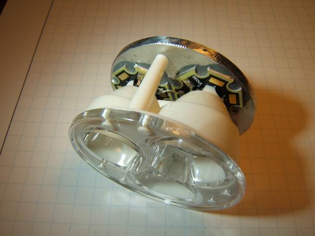
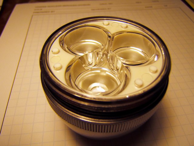
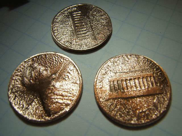
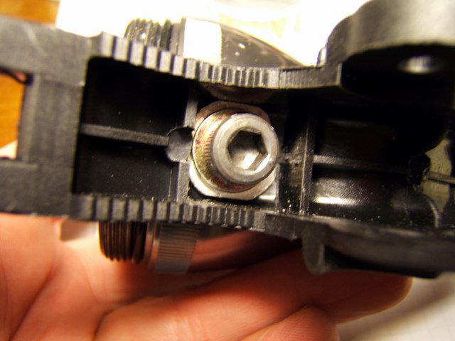
(Update) The above assembly procedure results in an unit that sits just slightly below the lip of the Mag-lite head. Subsequently the lens bezel does not force the tri-optic assembly down enough to make tight thermal contact with the land in the Mag-lite head. I had to use an O-ring as a spacer between the bezel and the lens cover to force the tri-optic assembly down tightly. I had to split the O-ring to get the proper diameter. This is seen in photo 1 below. In another Mag-lite conversion I used copper pennies as spacers under the LED stars to raise the LED up enough to allow the bezel to properly seat the optic assembly. The pennies (must be prior to 1982 to be copper) were cleaned and burnished with a high speed wire brush as seen in the photo 2 below. Arctic Silver epoxy was used to bond the LED stars and pennies to the heat sink plate, as seen in photo 4 below. Otherwise the assembly instructions can be followed with the inclusion of the pennies.
![]()
![]()
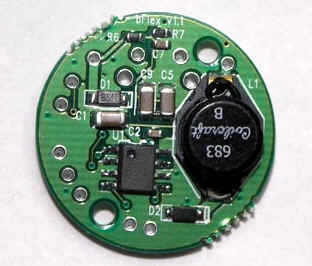
For a really good current regulator I used the bFlex UIB2 programmable regulator shown below in two photos. It costs $34, but it has better regulation than the cheap DX regulators and the interface was designed for bike lights. It is programmable so you can set up brightness levels, battery low warnings, temperature high warnings and strobe modes. The printed manual is 15 pages. I set it up for 5 levels of brightness. I wired the bFlex so that I had an external switch and power connection that was detachable.

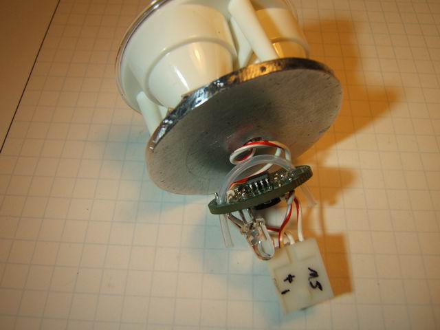
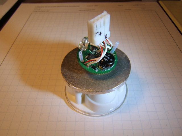
I tried various combinations of the Mag-lite head with hacksawed extensions on the rear , but nothing worked well. Pieces that screw together and have components attached, tend to get wires twisted during assembly. So I decided that for this prototype I would leave the bFlex loose in the back of the light. I used a Teflon tube that acted as a standoff (see photo above) to keep the bFlex from contacting the aluminum heat sink. ( The latest version of the circuit board does not have the large holes that I used to pass the Teflon tubing through.) That way the temperature sensor chip on the bFlex was still able to face the heat sink and monitor the temperature. I attached the red LED indicator on the board itself. The photos above show the assembly.
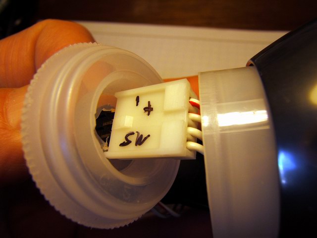
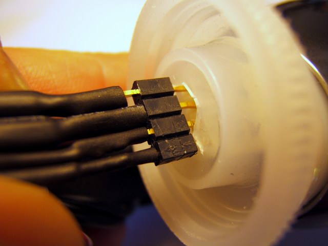
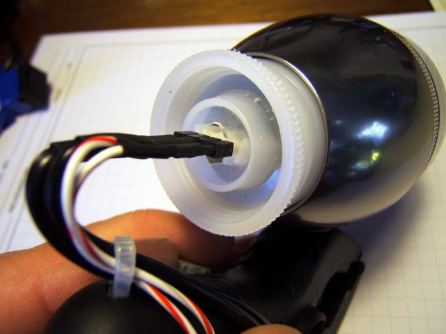
To electrically insulate the bFlex from the aluminum walls of the Mag-lite, I used a plastic film cannister which was able to be screwed into the rear of the Mag-lite head. Just another one of those lucky coincidences when you have enough junk laying around. The LEDs assembly was passed in from the front of the light. After the unit was assembled, the rear connector (homemade hack) with the switch and power cord was plugged into the bFlex. The cannister cap then closed of the rear light. The design is not waterproof but could be if required. The momentary contact switch was mounted on the side of the plastic clamp so that I could tap it with my left thumb while riding.

One problem with this design is the lack of a good heat sink, so the light heats up quite fast and even with a good breeze over the unit, the internals get hot enough to automatically reduce the power (I have the programmable trip point set at 80 C/176 F) to the LEDs. Even with the plastic cap off the back, the units heat up and reduces the light from full power to 1/3 after 15 minutes or so in a light breeze. This prototype obviously demonstrates that this Mag-lite “C” design does not have sufficient heat dissipation. Another difficulty associated with this design is the fuss factor wiring up the bFlex to the heat sink slug and rear connector. Bonding the star LEDs on the aluminum plate is an exact process. There is not much room for error, the lens must fit exactly and tightly over the LEDs. The total height of the internal assembly was just shy of the available space when the bezel is screwed down. So I had to insert a makeshift o-ring for a spacer to keep the heat sink assembly tight against the Mag-lite head. Heat sink compound mates the aluminum plate with the inside ledge to transfer heat to the Mag-lite head and pressure alone makes the thermal contact.
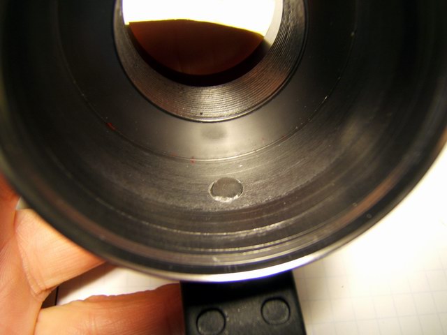
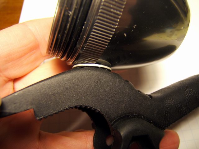
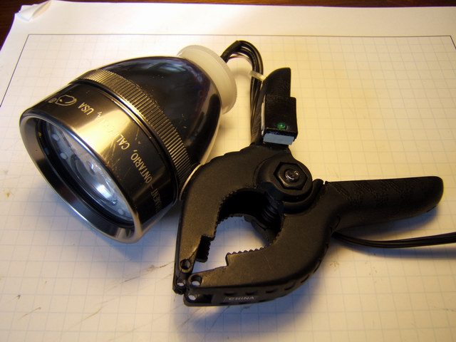
A hole must be drilled (before assembly) in the bottom of the Mag-lite head for the plastic clamp. It must be in a precise location and length to not interfere with the heat sink assembly. I had to grind the cap screw to the proper length. An operational difference for this prototype is that the controller requires a lot of clicking and pressing of the switch to change light levels. The rotary potentiometer in the other prototypes is quicker to vary, but not as precise. The beam for this tri-optic is a sharply defined round, evenly distributed cone pattern of about 30 degrees. I don't think the light output is as great as the aluminum angle prototypes.